SStructure-from-motion PPoses LLevelling OOptimisation OOrientation GGaussians EExport
I flew a drone over two spots six days apart and turned both flights into one photorealistic 3D reconstruction. Then I built a viewer so you can fly the original paths back through it in a browser, with the real video next to it.
of 7,471
3D points
error
shipped asset
in flight altitudes
I flew a DJI O4 Pro over two sites and built 3D Gaussian Splatting reconstructions from the raw footage, all on an Apple Silicon Mac with no CUDA. The pipeline goes video → gyro-driven frame selection → COLMAP structure-from-motion → Brush, a Rust/WebGPU 3DGS trainer → a WebGL viewer that replays the original flight paths through the reconstruction next to the source video. Along the way I implemented the 2DGS depth-distortion loss in Rust and CubeCL from the paper and merged two sessions six days apart into one coordinate frame. Most of my time went on one visual bug.
The bug was that the ground looks see-through when you fly low. It
turned out to be const znear = 0.2 in the viewer, one line. By
then I had already built and measured four separate fixes on the
reconstruction side, none of which could have worked, because I was aiming at
the wrong thing. I have left all of that in, because it was most of the work.
Capture, and which frames to keep
Consumer FPV footage is about the worst thing you can hand structure-from-motion. It moves fast, the shutter rolls, the lens is a wide fisheye, and the camera is bolted on pointing up, so you only ever see the ground at a grazing angle.
None of this was a choice. It's what the hardware and the footage are.
| Constraint | Consequence |
|---|---|
| No CUDA. Apple Silicon only, 48 GB unified | Rules out every mainstream 3DGS implementation. Brush, a Rust/WebGPU trainer, on the Metal backend. COLMAP runs CPU-only. |
| Consumer FPV footage, not a capture rig | No turntable, no controlled orbit, no even coverage. Camera pitched up 15–29°. |
| Two sessions, six days apart | Different light, different vegetation. Merging them meant proving cross-session matches existed before spending eighteen hours of mapper time. |
| A 4 GiB single-buffer limit on the GPU | A hard ceiling near 23.7 M splats at ~181 bytes each. Nothing to do with the 48 GB of system RAM. I found it by crashing into it. |
| Everything runs locally | One training run is 5–28 hours, so the slow part is deciding what to test, not the compute. |
Pull per-frame quaternions out of the DJI telemetry stream.
Keep a frame once the camera has turned far enough.
Decode the kept frames at 1920×1440.
Features, matching, incremental mapper, bundle adjustment.
Brush on Metal, 20k–60k iterations, 8M–22M splats.
Level, centre, scale, cap, and write a 32-byte-per-splat file.
Selection follows rotation, not the clock
Every nth frame is the obvious approach and it's wrong here. Flying
straight barely changes what the camera sees. A fast yaw changes everything in a
tenth of a second. So the selector waits for the camera to turn a set amount,
then keeps a frame. A floor of kmin stops it grabbing two
neighbours, a ceiling of kmax keeps the straights sampled.
I shipped 8°, kmin 2, kmax 15, which takes
7,471 frames out of about seventy thousand. Push the threshold up and the kept
ticks pile into the turns and vanish on the straights, which is what the time cap
is there to stop.
One check exists because something broke without telling me. DJI sometimes writes the telemetry with an identity quaternion on every sample. Two clips came out like that and the extractor reported success both times: the angle between identical quaternions is zero, so selection silently falls back to the time cap. It now counts distinct quaternions and refuses to run if there is one.
Structure from motion, and merging two sessions
Two sites, flown six days apart, rebuilt into one model. The thing I was actually worried about wasn't a bad merge. It was a silent one, where you get two disconnected chunks sitting in the same file and everything looks fine until you try to fly from one to the other.
Rung 0 is a registered frame at the height I was flying, the same kind of render as the right half of Figure 1. Every rung above it is a camera that never existed. It holds up because the geometry came from thousands of overlapping views.
Proving the merge was possible before paying for it
A merged mapper run takes eighteen hours. Before burning that to find out it wouldn't work, I ran the feature matching alone and counted verified two-view geometries between hilltop and cemetery frames. A few hours, and it answers the only question I had: is anything linking these two sites at all?
The merged mapper then gave me one model instead of two pieces, and registered 7,470 of 7,471 frames.
| Quantity | Value |
|---|---|
| Source clips | 9 |
| Frames registered | 7,470 / 7,471 |
| Triangulated 3D points | 3,359,339 |
| Mean track length | 6.58 |
| Observations | 22.1 M |
| Mean reprojection error | 0.821 px |
| Mapper wall time | 1,076 min |
This is where I lost most of a week. Brush writes a Vertical axis comment
into its PLY with Z negated, and getting the up-vector backwards buries every
camera underground while the viewer still looks normal. I now derive up from the
ground geometry and check it by asserting the cameras are above the
terrain: right sign, 1% of cameras below; wrong sign, 99%. The check itself then
broke, because the terrain fit behind it only fits one height field. On a
two-site scene it stretches across the gap and reports 52% underground, plus a
tidy-looking 1.2% hole figure I nearly believed.
Rendering, and replaying the flights
The viewer sorts a few million splats back to front and alpha-blends them. There's no depth buffer in it anywhere. Almost everything in the rest of this write-up comes back to that, including the bug.
Each splat is 32 bytes: position, scale, an 8-bit colour, an 8-bit quaternion.
One instanced quad each, with the 3D covariance projected to a 2D ellipse every
frame. Order comes from a 16-bit counting sort by depth, re-run in a worker
whenever the view turns far enough to matter. The blend is
ONE_MINUS_DST_ALPHA / ONE, front-to-back "under"
compositing, so destination alpha is accumulated coverage.
Flying the recorded trajectories back through the model
The replay is the part I'm happiest with. The viewer recovers the exporter's
transform by least-squares fitting it from the camera set, to a maximum position
residual of 3.03e-14, then flies the original trajectories through
the reconstruction as coloured ghosts with the source video in a corner at the
same pose.
Time has to come from the frame index in the filename, not the pose order. Selection was adaptive, so poses bunch up in the turns and thin out on the straights. Played at a fixed rate per pose the drone crawls through corners then teleports down the straights.
The blend operator also won't let you draw in the obvious
order. Drone models first, splats on top, doesn't work at all. Anything
in the buffer at alpha 1 makes every splat after it multiply by
(1 − 1) and the scene vanishes. So it's a depth prepass
instead: ghosts fill depth with colour writes off, splats draw with depth testing
on and writes off, ghosts draw again in colour underneath. Occlusion comes out of
the blend operator on its own.
The ground was see-through
When I flew low in the viewer, the bottom third of the frame showed the background through the ground. It made the whole thing feel broken no matter what the numbers said, and chasing it is most of what this project turned into.
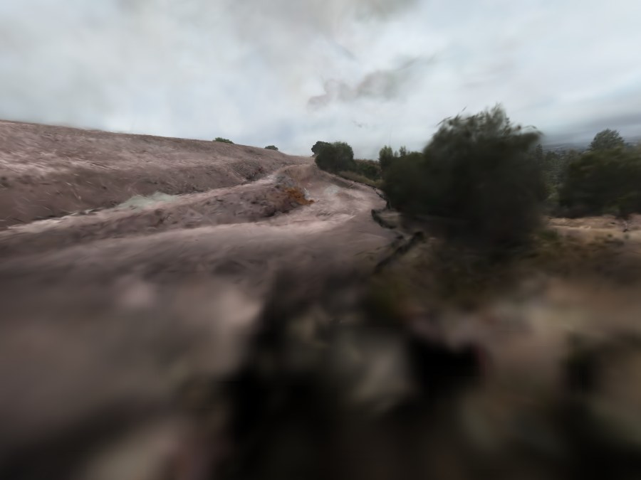
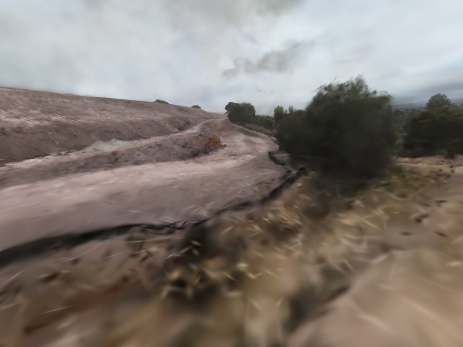 znear 0.2, shipped
znear 0.01
znear 0.2, shipped
znear 0.01
0053_001085), everything identical except the near plane.
Bottom-third holes go from 51.2% to 4.4%, and accumulated
opacity from 0.520 to 0.897. The black isn't dark ground. It's nothing at
all reaching the pixel.
What I tried on the reconstruction side
I was convinced this was a reconstruction problem, and I had numbers backing me up. The ground really is a slab and not a surface: 47–49% of its opacity mass sits below the visible surface, the 10→90% opacity transition spans 131–156% of median flight altitude, splat opacity has a median of 0.26 with 83% under 0.5, and the thin axis sits a median of 47° off the surface normal. All true. None of it is why the ground was see-through.
- A flatness prior at refine time. Squash each splat toward a disc. Made it worse: holes went 33.5% → 38.9%. Flattening after export was worse again, 35.9% → 61.3%.
- A depth-distortion loss. Written from the 2DGS paper in Rust and CubeCL. §6. A measured negative.
- A screen-space covariance dilation. Null at 3.3× the value the trainer actually uses.
- A post-hoc opacity boost. This one worked, but only as a patch over the symptom. I took it out once I found the real cause.
The flatness prior taught me the most, and the lesson is one line of arithmetic I never did. A ground splat's thin axis is about 1.0% of flight altitude; the slab it sits in is about 125%. The slab is 129 times thicker than a single splat. So the problem is where the splat centres are, and anything that rescales the axes is aiming at the wrong number. Two minutes with a calculator would have killed the whole category before I wrote any of it.
The actual cause
It was const znear = 0.2;, one line in viewer/main.js.
Splats are frustum-culled on their centre depth, and the reject
test pz < −margin·z reduces for this projection matrix to a pure
near-depth cut:
zfar 200 and margin 1.2 the cut lands at z < 0.0910 for znear 0.2 and z < 0.0045 for znear 0.01. The margin divides it by about 2.2, so the shipped cull was never at 0.2. It was still well inside where I was flying.
Median flight altitude on these scenes runs 0.24 to 0.47 in viewer units. A cut
at 0.091 sits inside that, and when the camera is low it takes the ground right
underneath it. The viewer has no depth buffer, so znear was buying
nothing anyway and shrinking it cost nothing.
Try it
A real splat renderer, not a video: same format, sort and shaders, on a 208,000-splat crop taken around one low capture pose. The view presets are real COLMAP poses and Fly the recorded path follows eighteen seconds of the actual flight. Drag the near-plane control to watch the ground disappear underneath you.
Why it hid for so long
I actually tested znear early on and dismissed it. My note in the
log says "lowering znear to 0.01 moved bottom-third opacity by <0.03". That
number was a cohort mean.
Every tool I'd built reported an average: the measurement script a cohort mean, the slab profiler three hundred ground columns, the detail metric forty frames. The bug lived in the tail, and averaging it across a cohort that's mostly fine turns a thirty-six-point effect into nothing. Anyone flying the viewer spots it in two seconds, because they fly through the bad poses instead of averaging over them.
Two measurements had been pointing straight at it and I misread both:
- corr(alpha, splats per pixel) = +0.94, but corr(alpha, splats within 0.3 of the camera) = −0.46. More geometry near the camera, less alpha on screen. If the geometry is there and isn't showing up, something has to be throwing it away, and culling is the only thing that does that. This sign flip was sitting on my results page before I ever swept the near plane.
- corr(alpha, altitude) = +0.35. The lower I flew, the worse the holes got. That's what a fixed near plane does. A diffuse slab wouldn't care how high I was.
The part I found hardest to accept came later: how bad the bug looked came down to the scene's normalisation, not to how I flew. The exporter scales every scene so the camera p90 radius lands at 3.0, which gave the cemetery a median altitude of 0.24 and the hilltop 0.47. Same drone, same day, same pilot, and one scene got hit twice as hard because of a constant in the export step.
A depth-distortion loss, written in Rust
Brush ships no surface regulariser, and 3DGS has nothing that pushes a surface to be thin. Looking along the ground, a thick see-through slab and a thin solid surface give the same image, so they give the same loss. The optimiser has no reason to prefer either.
So I implemented the depth-distortion term from the 2DGS paper. For each ray, you penalise how spread out that ray's own contribution is along its depth.
w = α·T is the blend weight and t is the depth.Aᵢ = Σ_{j<i} wⱼ and Bᵢ = Σ_{j<i} wⱼ tⱼ. The rasteriser already goes in depth order, so both prefix sums come for free.The backward pass is where it gets interesting
The gradient needs a suffix sum as well as a prefix sum, and the
backward rasteriser walks front to back with no second pass. The suffix sum
falls out of Euler's theorem, since L is homogeneous of degree 2 in
w:
R_{k+1} = R_k − w_k g_k. No second pass and no extra storage per splat.ΣW and ΣWt in two spare output channels, so the backward pass can work out what's behind splat k without ever looking at it.
Alpha reaches the loss by two routes: directly through
wᵢ = αᵢ·Tᵢ, and indirectly because every Tⱼ for
j > i carries a (1 − αᵢ) factor. Miss one and the
gradient comes out slightly wrong instead of obviously broken, which is much
harder to notice.
Two traps here, both silent. I widened the gradient buffer
stride from 10 to 11 unconditionally instead of only with the loss on;
two kernels disagreeing about a stride gives you quiet corruption, not a crash.
The other was an early-out in the projection backward,
if !any_grad { return }, which would have dropped depth-only
gradients without a word. Checked with finite differences, plus an assert that
the gradient is non-zero, because a finite-difference test passes fine
when both sides are.
And it did not help
At weight 0.05 with no normalisation it crushed the scene's depth range: splat
radius p99 17.45 → 7.78, PSNR 22.14 → 19.80 dB. The term is degree-1 in
t with no upper bound, so rays through distant geometry have a
bigger absolute depth spread and dominate the gradient. Per-ray normalisation
stopped the collapse and still made detail worse, 22.6% → 16.9%.
The implementation is right and it just doesn't help here. I was also aiming it at a problem that turned out to be the viewer's fault.
Near-field blur, and a metric that lied about it
With the transparency fixed there's still a second problem, and this one is real: the ground close to the camera is blurry. The obvious way to measure it mixes it up with something else entirely.
My sharpness metric divides render high-frequency energy by ground-truth high-frequency energy, region by region. Bottom third 18%, top half 40%, which looks like a disaster in the near field. Except the bottom third's ground truth has 2.44× the high-frequency energy in it, because it's close-up grass and the top half is sky and distant hills. I was never comparing like with like. Grass at two metres isn't multi-view consistent anyway: the blades block each other and shift as you move, and no number of splats reconstructs that.
What separates them is binning 8×8 blocks by their own local ground-truth texture and comparing near against far at matched difficulty.
A controlled ablation
Five runs on the cemetery scene, all 20,000 iterations on the same learning-rate schedule so they could be ranked against each other.
What the ablation changed my mind about
A cap being saturated tells you it binds. It doesn't tell you that lifting it helps. Every run I'd ever done exported exactly 8,000,000 splats, and had been doing that since iteration 10,000. I took that as obvious proof the cap was what was holding me back. Then I gave it a 16 M budget and the optimiser only took 8.67 M by the same iteration. So the real gap was 8.0 against 8.67, not 8 against 16.
The flag that turned out to matter had never once fired.
--split-at-screen-size defaults to 0.5, but the distribution has a
p99 of 0.103 and only 0.01% of splats clear 0.5, so nothing was ever force-split.
And those splits are paid for out of max_splats − current, zero
since iteration 10,000, so lowering the threshold alone would also have done
nothing. The two flags only work together, which is why testing either one alone
got me nothing.
Resolution isn't the answer either, and my metric lied about it by default. Training at native 2688 scored 20.2% on a common yardstick, a dead tie with 20.3% at 1920. Against its own 2688 ground truth it scored 16.1%: it didn't resolve more detail, it failed by the same proportion at a harder target. The metric had originally given it 19.7%, because it grabbed the first ground-truth directory alphabetically and upscaled a 1920 reference to match a 2688 render, scoring against a reference with no detail above 1920's Nyquist.
The final run, and the mistake that undid it
I took the config that won and ran it for 60,000 iterations on the merged scene: 28 hours, 16 M splats, all 7,470 cameras. The texture improved exactly like I said it would. It also looked obviously worse.
Bottom-third detail went 14.8% → 16.6%, the top half 34.7% → 35.6%, near-field detail improved in every texture band and the near/far ratio rose in five of six. And the ground was see-through again.
The export step, not the training. The exporter keeps the top N splats
by opacity × projected area. The old run kept 3 M out of 8 M, the new one 3 M out
of 16 M: I'd doubled the trained splat count and left the cap alone, so it went
from throwing away two thirds to four fifths. --split-at-screen-size
had also made every surviving splat smaller. Both cut coverage.
I made the same metric mistake twice in one project. Sharpness measures texture; the hole metric measures whether a ray picks up any alpha. Different failures, and they can move in opposite directions. I gated a 28-hour run on the first and never checked the second, which is the same mix-up that made a blur problem look like a transparency problem earlier. The build that ships is still the 8M / 30k one.
Everything that did not work
None of this worked. It's here because it was most of what I actually did, and I checked it as carefully as the parts that did.
| Intervention | Measured outcome |
|---|
Engineering notes worth keeping
- LPIPS was broken, then too slow, then actively bad. It panicked four seconds into training. The Burn fork tracks autodiff-ness at runtime in an enum instead of in the type, so weights loaded from a record come back as plain float variants and the first op mixing them with autodiff activations calls
.autodiff()on a plain tensor. Fixed by lifting each parameter throughTensor::from_inner. Then it ran at 29 s/iter against roughly 0.5 for the whole rest of the step, so a 20k run would have taken months. A random 256 px crop made it affordable, and it hurt quality anyway. - A 4 GiB single-buffer ceiling, not a RAM ceiling. A 24 M-splat run died with
failed to reserve 4336857088 bytes. That is just past 4 GiB; at ~181 bytes per splat the hard ceiling is about 23.7 M splats, on a machine with 48 GB of RAM. - A wait loop that lied to me.
until pgrep -f 'a\|b'exits straight away and prints its success message, becausepgrep -fwants an extended regex where alternation is a bare pipe. It told me every scan had finished while three renders were still going. - Don't edit a bash script while it's running. Bash reads the file as it goes, by offset, so an edit mid-run can make it resume in the wrong place. Every chain script here got killed by PID, edited, checked with
bash -n, then relaunched. - A scoring bug that looked like a result. The comparison script had hardcoded ground-truth paths, so on any newer frame set it printed
images: 0, which reads like a finding instead of a broken path.
Limitations
- Near-field blur is still there. Bottom-third detail retention is 14.8% on the shipped merged build, against 34.7% for the far field, and my ablation moved it by two points. It's a scale problem, not a capacity one, and I don't have a fix for it.
- Some holes survive at a few poses. The worst 1.5 M cemetery pose is still at 26% even after the near-plane fix, so there's real missing geometry near the camera underneath the rendering bug.
- Two sites, one day each, one drone. I haven't shown this works on another camera, another lens, or a differently shaped scene. The floater filter that works on open terrain deletes real ground on a dense city scene, and the other way round.
- The ground is still a slab. 47–49% of its opacity mass sits below the visible surface. That measurement is fine. It just wasn't causing the thing I was using it to explain.
- The interactive above is a crop. 208,000 splats out of 3,000,000, picked around one pose, with the sky culled. The full asset is 96 MB, which is not something I'm putting on a portfolio page.
What I'd take from it
- The average hid it. The bug that drove this whole project got measured early, averaged across a cohort that was mostly fine, and dismissed in one line of my notes.
- Texture and coverage both sound like "quality" and they moved in opposite directions. Optimising one quietly wrecked the other, twice.
- Do the arithmetic before building anything. One line ruled out four interventions I had already written.
Tools
COLMAP 4.1.1 on CPU. Brush (Rust / WebGPU / Metal) with Burn and CubeCL. Python, NumPy, OpenCV and Pillow for the analysis, including a CPU splat rasteriser I wrote from scratch that copies the viewer's projection, covariance, half-float packing and blend arithmetic exactly. It's how I tested rendering ideas without a GPU, and the only reason Figures 1 and 2 exist. The viewer is WebGL2, extended from the antimatter15 splat viewer. Then ffmpeg, and a pile of bash scripts running GPU-serialised job queues.